Now that I've discussed the general concepts and the problem statement in part 1, it's time to talk hardware details. There are three primary hardware components: the Raspberry Pi, the lights (described in part 1), and an interface board to connect the two.
The Raspberry Pi, pictured below, is a credit-card sized computer featuring an ARM SoC (System on a Chip) from Broadcom, HDMI, USB, Ethernet, analog and digital audio out, and direct access to the built-in SoC peripherals via headers.
 Raspberry Pi
Important for this project is the GPIO (General Purpose Input Output) pins on the main header in the upper left corner of the board. I'm using two of these pins to control the two sets of lights. Setting them low (0V) turns on the lights and setting them high (3.3V) turns them off.

The logic is inverted because the first two GPIO pins have pull-up resistors built into them. A pull-up resistor is a resistor, typically in the tens of kohms, that connects a logic pin to vdd (3.3V). Pull-up and pull-down (connected to ground) resistors are used to stabilize logic pins, such as GPIO. When a pin is configured as an input, or is first powering up, the voltage tends to float around all over the place. By connecting a fairly large resistor to either vdd or gnd, it will prevent the pin from floating and lock it to whatever voltage the resistor is connected to. Since it has a relatively large resistance, when the pin is switched to an output and the chip more or less connects it directly to vdd/gnd, the resistor acts like it isn't there. Using inverted logic is the more sensible route here because the Raspberry Pi uses pull-up resistors, meaning things are going to be logic high by default, which we want to be off.
With the signals, we still need a way to convert 3.3V to 0V and 0V to 12V. In addition, the Raspberry Pi can only output up to 16mA, which is way way way below the 1.2A needed to power the daytime lights. This is where the interface board comes into play.
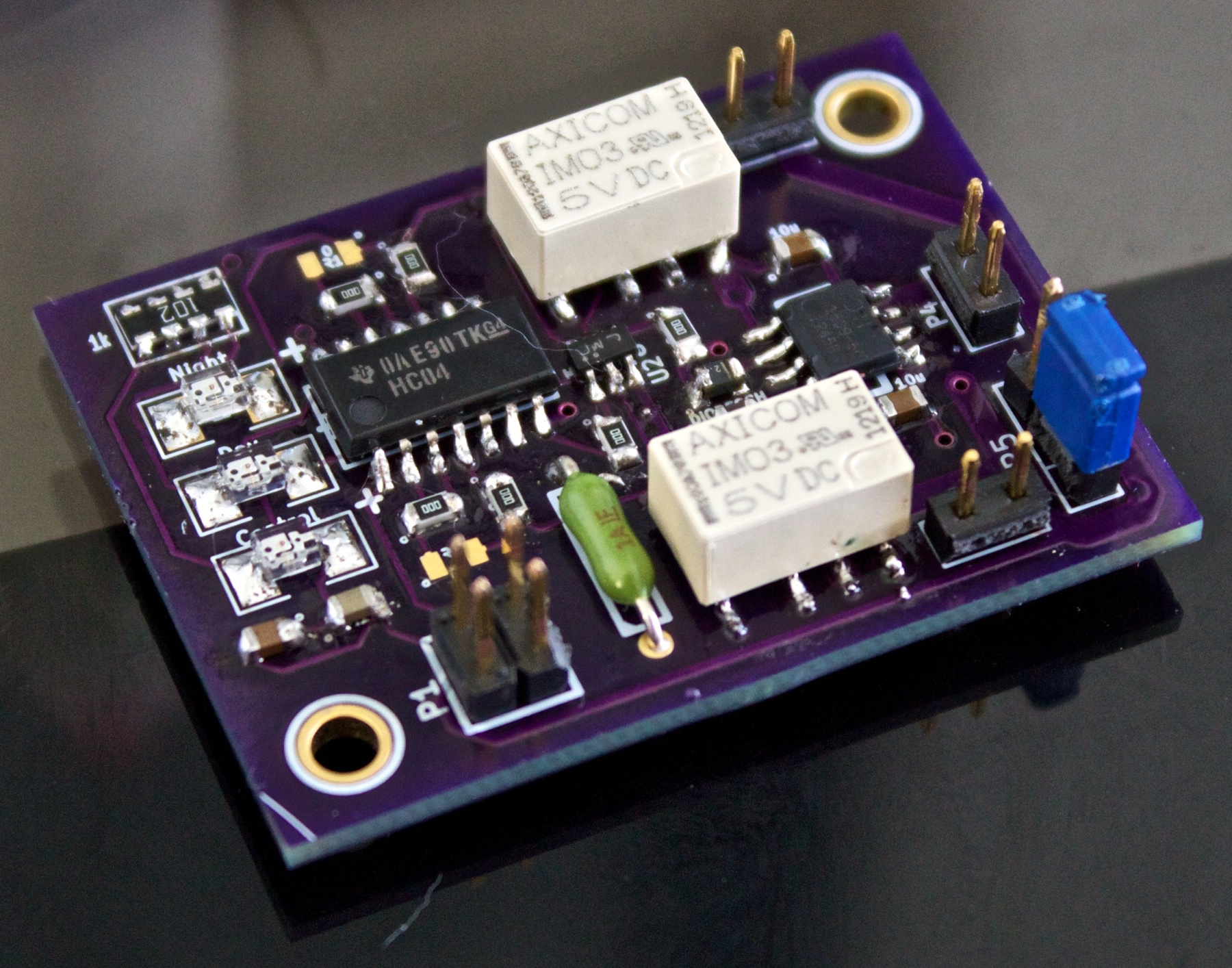
The interface board is a custom board that I designed using KiCAD and had manufactured by OSH Park, both of which totally rock! This part of the project took by far the most time and money. I ended up going through three revisions of the board before I got something that worked properly. I did a blog post on the first version of the board back in May, for reference. Admittedly this is mostly due to me being rusty at board design, considering that I haven't done any board design of any sort since college. The results are working very well though, so no complaints!
The board works by first running the Raspberry Pi signals through an inverter. This serves two purposes: it inverts the signals back to non-inverted logic, and it also buffers the signals, helping to protect the Raspberry Pi. The output of the inverter is connected to the base of a load driver, which is basically just a BJT (Bipolar Junction Transistor) that turns on and off. Connected to the source is a SPDT (Single Pole Double Throw) non-latching relay with a 5V switching voltage regulator powered by the 12V aquarium power supply on the other end. When the input to the load driver is 0V, the transistor is pretty much an open circuit, meaning that the relay sees 5V on either side of its coil contacts and is thus in it's "off" position. When the input to the load driver is 3.3V (or so), the transistor is pretty much a short circuit, so the relay sees 5V on one side of the coil and 0V on the other and is thus in it's "on" position. Connected to the switch is the 12V power supply from the aquarium on one end and the lights on the other.
There are a few other pieces added to the interface board. A 3-way switch is connected that can a) disconnect power from the interface board, thus disabling the entire system, b) connect power to the interface board such that it is operating as described above, or c) bypasses the interface board and directly connects the daytime lights to the power source (useful for maintenance). There are also some diagnostic LEDs that show which light is currently on (if any) and whether or not power is connected to the interface board. There are also a few fuses, protection diodes, and filter capacitors spread around the board.
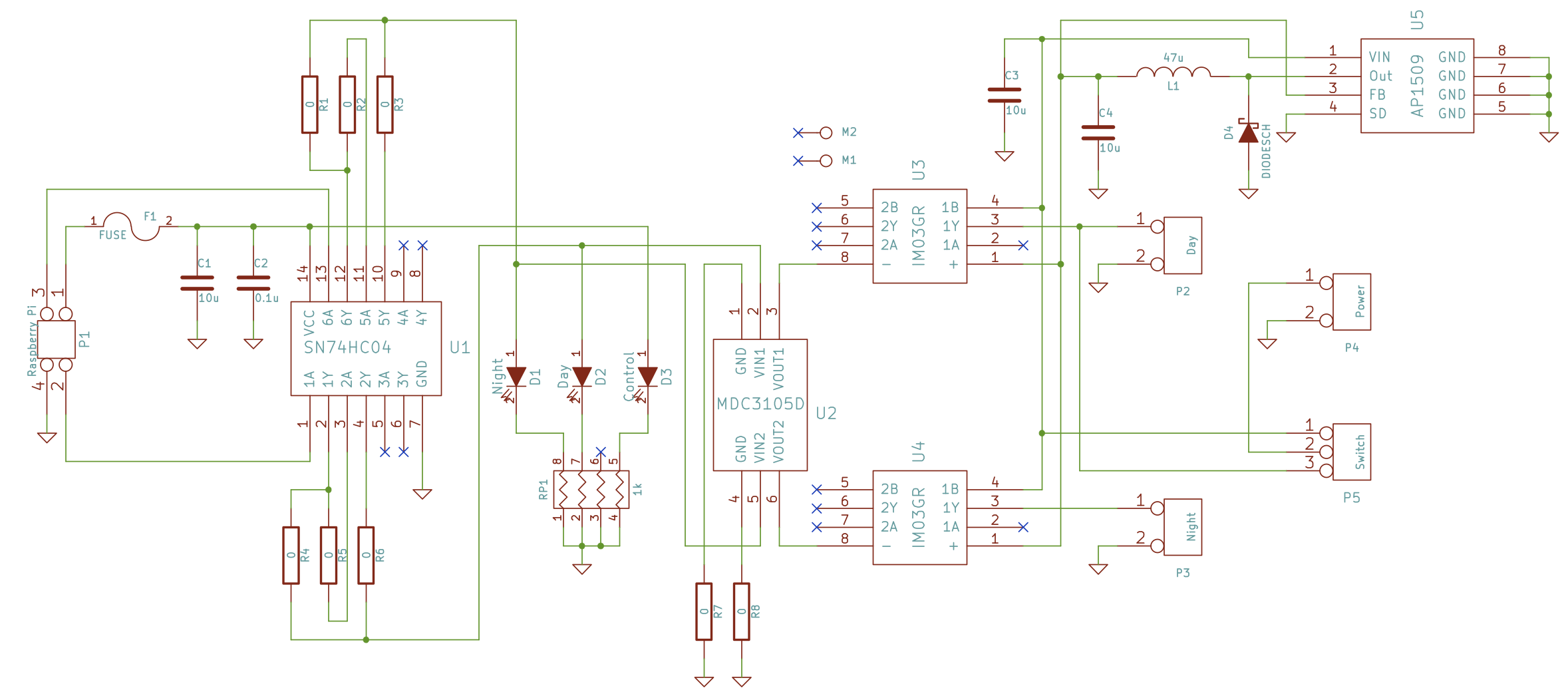
Here is the schematic for the board:
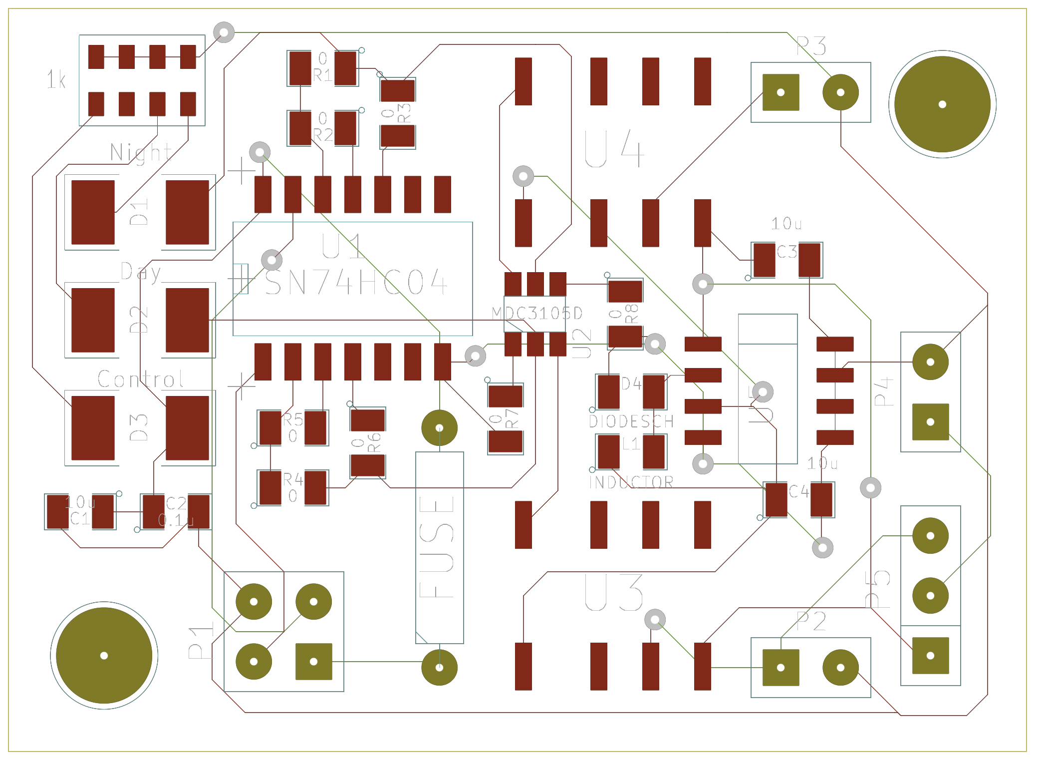
Here is the layout for the board:
And finally, here are some pictures of the board in all of its purple glory: